Overview
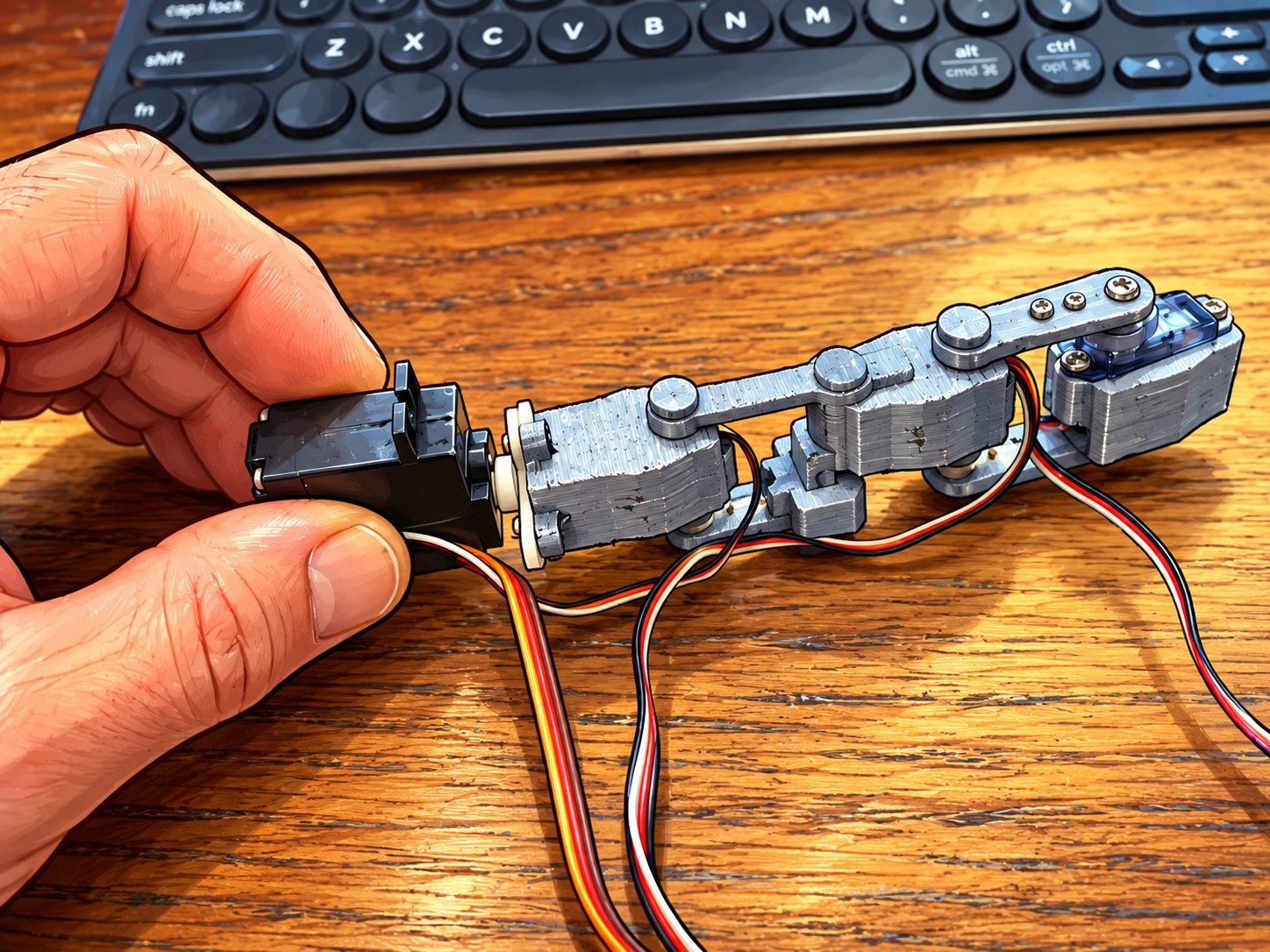
Fabrication at WEZLAB is where software and ideas become physical objects. This project focuses on a small articulated robotic finger built from printed components, servo hardware and mechanical linkages.
The aim is not simply to print a finished part. The useful work is in the iteration: changing geometry, checking clearances, testing movement, observing where the mechanism binds, and using each physical version to inform the next design.
Model the mechanism
Design printable components around real servo dimensions, pivot points and linkage travel.
Turn geometry into hardware
Produce tangible parts that can be handled, assembled and tested rather than judged only on-screen.
Let the mechanism answer
Movement reveals interference, flex, leverage and alignment issues that are difficult to see in CAD alone.
Finger Animation
This animation shows the articulated finger model in motion and makes the relationship between the servo input, linkage geometry and individual finger segments much easier to visualise.
Servo-driven linkage concept and segment movement.
The Prototype
The current build combines a compact servo with multiple printed finger sections and an upper mechanical linkage. Each section must move in a coordinated way while remaining simple enough to print, assemble and revise.
Servo interface
The actuator provides the initial motion. The printed connection must transfer that movement without slipping or introducing unnecessary play.
Segment pivots
Each joint needs enough freedom to articulate while retaining predictable alignment through the full range of motion.
Linkage geometry
The upper linkage translates servo movement across the finger. Small dimensional changes can significantly change the resulting curl.
Printable tolerances
Real printed parts have layer lines, friction and dimensional variation. The design must work in the physical world rather than only in the CAD model.
Design Loop
The fabrication workflow is deliberately iterative. Each version is treated as a test instrument.
Sketch the requirement
Identify the mechanical problem: mounting, articulation, clearance, strength or motion transfer.
Model in CAD
Create or revise the part geometry, paying particular attention to real hardware dimensions and pivot relationships.
Slice and print
Convert the model into printable geometry and produce a physical version quickly enough to keep the iteration cycle short.
Assemble and move it
Fit the servo, fasteners and linkages and observe the actual range of motion under real mechanical constraints.
Revise
Feed the result back into the CAD model and repeat. The workshop becomes part of the design process.
Workshop Observations
Physical prototypes expose hidden assumptions
A linkage that looks clean on-screen can reveal unexpected interference, leverage or flex once assembled.
Small geometry changes matter
Pivot position, hole spacing and linkage length can alter the entire movement profile of an articulated mechanism.
Printability is part of engineering
Orientation, wall thickness, tolerances and support requirements influence whether a mechanically correct design is actually useful.
Animation improves understanding
Seeing the intended movement before or alongside the physical build makes it easier to reason about how each component contributes to the mechanism.
Next Iterations
The robotic finger is part of a broader progression toward more capable hand mechanisms. Future revisions can refine linkage proportions, servo integration, joint clearances, mechanical strength and repeatability while keeping the design practical to manufacture in the workshop.
The project remains deliberately open-ended: every version is both a working mechanism and a record of what was learned from the version before it.